The Electrical Power Subsystem (EPS) is responsible for designing the hardware systems that go into the satellite, as well as monitoring the power budget for these systems. We work with the other subsystems to develop a design which best fits their needs, while making sure requirements and limitations aren’t exceeded, such as power consumption during the mission. Development tasks that EPS members perform involve designing printed circuit boards (PCBs), simulating circuits in LTSpice to estimate power consumption, soldering components onto PCBs, and testing board functionality through voltage and power draw monitoring. Additionally, EPS writes code for interactions between onboard microcontrollers and the mission computer, in the form of a driver.
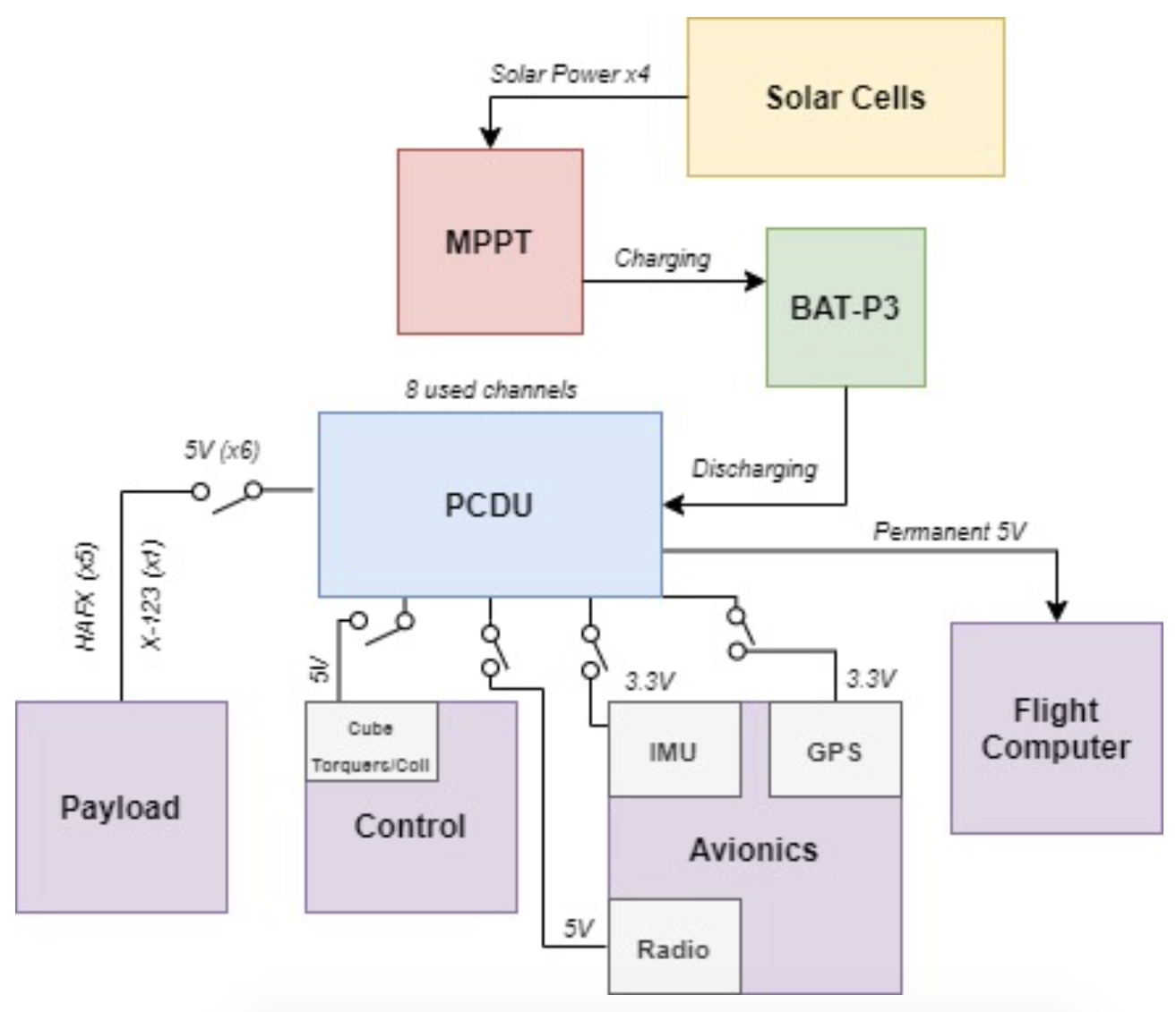
EPS consists of a lot of hardware that can be broken into two categories, the board stack and the power stack. The board stack is made up of the: Solar Array PCB, Flight Computer PCB, Avionics PCB, and Deployment PCB. These boards all have different purposes but are equally important to the functionality of the satellite. The power stack is made up of a maximum power point tracker (MPPT) that will deliver optimal operating voltage to the system, a power conditioning and distribution unit (PCDU) that delivers different amounts of power to different system components simultaneously, and a battery that will power the satellite.

Undergraduate researchers learn how to design functional PCBs, how to solder circuit components, as well as how to test hardware and furthermore understand their power characteristics.